
CAD design
Design for manufacture in CAD: how the model becomes a part that can actually be made
Design for manufacture: the process helps determine the geometry from the start. Basic rules, typical mistakes, and what data a manufacturer needs.
A CAD model can look perfect and still be unusable. At the latest when the manufacturer calls and asks how this undercut is supposed to be ejected from the tool, it becomes clear: the design was for the screen, not for manufacture. Design for manufacture prevents exactly that.
This post is about the basic rules, typical mistakes, and how I put that into practice in product development at KANID. A general overview of CAD design in product development is in the earlier post.
What does “ready for manufacture” mean?
To design for manufacture means shaping a part so that it can be made and assembled reliably and without special effort with the intended process. The core: the manufacturing process is set early and helps determine the geometry — not the other way around.
A holder made from sheet metal looks different from the same holder in injection moulding or from 3D printing. Anyone who designs first and then looks for the process usually designs twice.
Rules for design for manufacture, by process
The rules differ by process. A few examples that play a role in almost every project:
Injection moulding
- Uniform wall thicknesses. Sharp jumps in wall thickness lead to sink marks and warpage.
- Draft angles. Faces in the direction of ejection need a draft, otherwise the part jams in the tool.
- Avoid undercuts. Every undercut needs a slider in the tool — that costs money.
- Ribs instead of mass. Achieve stiffness with ribs, not with thick walls.
Machining (milling, turning)
- Internal radii. An end mill is round. Sharp internal corners in pockets do not exist without extra effort.
- Accessibility. Every face must be reachable for the tool, preferably in few set-ups.
- Tolerances only where needed. Tight tolerances on all dimensions drive costs without improving the function. For all other dimensions a general tolerance is enough; see ISO 2768: general tolerances.
Sheet metal
- Bend radius. The inside radius of a bend must not be chosen too tight; radii that are too small tear or become inaccurate. The permissible radius depends on the material and the sheet thickness and belongs in the design, not only in the workshop.
- Minimum flange length. After the bend, enough flange length must remain so that the sheet can be held in the tool and formed cleanly. Flanges that are too short cannot be bent reliably.
- Hole distance from the bend edge. Holes and cut-outs too close to the bend edge distort when bending. The distance must be large enough for the hole shape to be retained.
- Relief cuts. At corners where two bends meet, relief cuts are needed.
3D printing (FDM)
- Think about the build direction. The part is less load-bearing in the layer direction. How the part sits on the printer belongs to the design.
- Limit overhangs. Steep overhangs need support structures that have to be post-processed.
- Fits with clearance. For printed fits, clearance has to be planned in; how much depends on the printer and the material and is checked on the prototype.
More on what printed parts are good for in development is in the post Having a 3D-printed prototype made.
Design for assembly belongs with it
A part that can be made is not yet a product. The assembly also has to be put together. A few questions I ask myself here:
- Can the number of parts be reduced by combining functions in one part?
- Can a part only be installed in one orientation — or can it also be inserted the wrong way around?
- Do standard parts and bought-in parts come into question that are available from several suppliers?
The last point in particular often saves the most. A standard part from the catalogue is almost always cheaper and available faster than a special. That is why a parts list with sources of supply is already part of the result of phase 1.
Typical mistakes that become expensive later
- Process set too late. The geometry then does not really fit any process.
- Tolerances everywhere. Every dimension tightly toleranced, instead of only the functionally relevant ones.
- Thought only in the solid model. No drawing, no bill of materials — the manufacturer has to guess.
- Not tested. Assumptions about fit and function are only checked on the series part.
Against the last point, the prototype helps; against questions of strength, where needed, an FEM calculation in Onshape.
What data a manufacturer needs
At the end of a design there is not only a 3D model, but a data set with which a manufacturer can quote and produce:
- STEP files — a neutral 3D format that every common CAD and CAM system can read. Why STEP and not an STL is in the post STL or STEP?.
- Technical drawings as PDF — a drawing ready for manufacture states the functionally relevant dimensions with tolerances, a clear datum system for manufacture and inspection, and information on material and surface. Not every dimension is tightly toleranced.
- Bill of materials — all parts, standard parts and bought-in parts of the assembly.
Exactly these data I hand over at the end of phase 2, together with access to the Onshape project.
How I put this into practice at KANID
I design in Onshape. The CAD runs in the browser, and you review every design status via a link — without a CAD licence of your own. So you do not only see the result, but the path to it, and can intervene early.
At KANID, design is not a stand-alone assignment, but part of product development in two phases:
- Phase 1, concept & feasibility: requirements specification, solution concept, parts list with sources of supply, a short report on risks, and a binding fixed-price quote for phase 2. Fixed price 1,450 € incl. 19% VAT.
- Phase 2, development through to the pre-series prototype: CAD in Onshape, 3D-printed prototypes, 2 revision loops, FEM where needed, drawings, bill of materials and STEP data. Fixed price after phase 1.
Details of the process and prices are under Services; I explain the costs in the post Product development at a fixed price: cost and process. Whether a design can be funded through the innovation voucher is a separate question: contract developments and standard industry design services are excluded by the L-Bank information sheet. The post Innovation voucher Baden-Württemberg: what is funded and what is not summarises the rules.
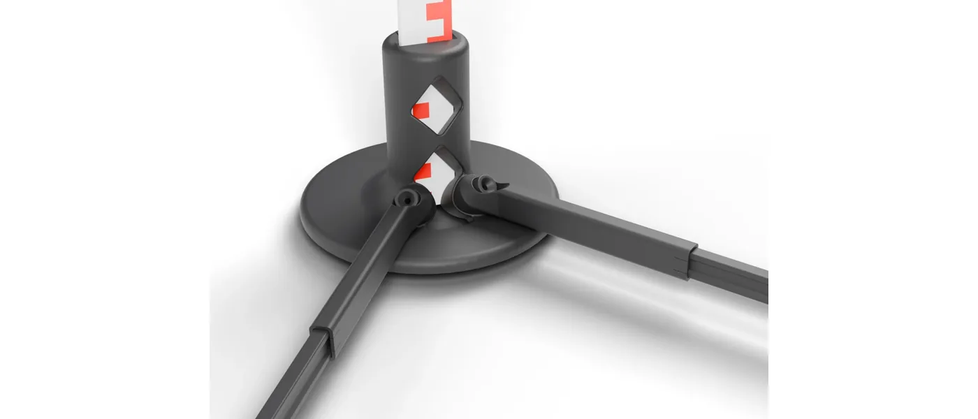
An example from our own development: the SoloMeter 2.0 is manufactured by FDM 3D printing and has a three-foot system and a built-in vial. You can rotate the 3D model in the browser on the References page.
In brief
What does design for manufacture mean?
Designing a part so that it can be manufactured and assembled reliably, without special effort and at acceptable cost, with the intended manufacturing process. The process is therefore set early and helps determine the geometry.
What data does a manufacturer need?
As a rule, a neutral 3D format such as STEP, a technical drawing as a PDF with the functionally relevant dimensions and tolerances, and a bill of materials. KANID hands over exactly these data, and in addition access to the Onshape project.
What makes a technical drawing ready for manufacture?
It states the functionally relevant dimensions with tolerances and a clear datum system on which manufacture and inspection are based. Not every dimension is tightly toleranced. Together with the STEP file and the bill of materials, that is the data set a manufacturer needs.
In which CAD system does KANID design?
In Onshape. Customers review every design status via a link in the browser, without a CAD licence of their own.
Does KANID offer CAD design alone as a service?
At KANID, design is part of product development: from concept and feasibility through CAD and a 3D-printed prototype to the pre-series prototype, in two phases at a fixed price.
Conclusion
To design for manufacture means thinking about manufacture from the start: set the process, align the geometry with it, apply tolerances deliberately and check them on the prototype. That saves loops at the manufacturer and money in series production. If you would like a product developed, write to me via the contact form.
design for manufactureCAD designdesign servicesOnshapeSTEPtechnical drawing